conceptskasce.blogg.se

Smith chart impedance


4: Input Impedance with Transmission Line Practically, the trajectory may be similar to the purple area because of non-perfect matching.įig.

smith chart impedance

The intersecting point is the origin of the Smith Chart.
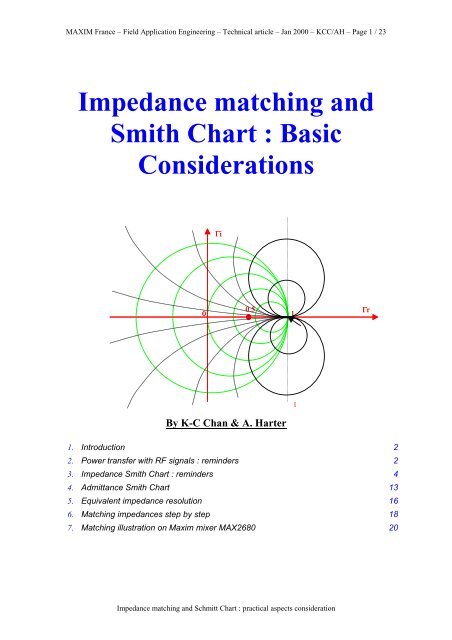
  • The red x-y aisles represents the real and imaginary part of G.
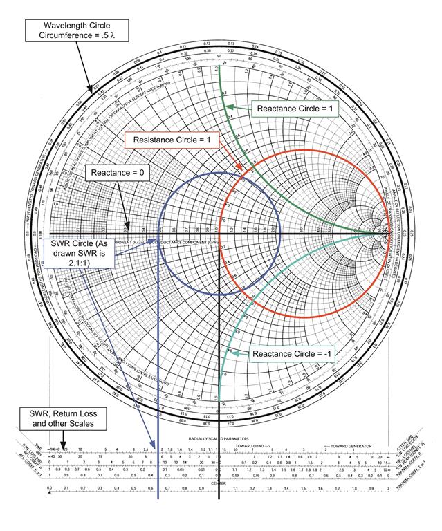
  • The keys are complex reflection coefficient, G, and normalized impedance, z, are plotted on the same chart as shown in Figure 1. Please refer wiki's Smart Chart for details and this reference. With relatively simple graphical construction it is straightforward to convert between normalized impedance and the corresponding complex voltage reflection coefficient. Normalized scaling allows the Smith Chart to be used for problems involving any characteristic impedance or system impedance, although by far the most commonly used is 50 Ohm. The Smith Chart is plotted on the complex reflection coefficient plane in two dimensions and is scaled in normalized impedance (the most common), normalized admittance or both. That is, Smith Chart is a very useful tool to solve most electrical problems. The majority of EM wave and waveguide either belong to the TEM domain or can be approximated by TEM wave. Smith Chart (transmission line) is based on a specific EM wave called TEM (transverse EM) wave where the dynamic electrical and magnetic fields are perpendicular to the wave propagation direction. Lumped circuit is a subset included in Smith Chart.

    smith chart impedance

    A brief introduction of Smith Chart is on the other article. Luckily, there is a another tool originally derived from transmission line, namely Smith Chart, provides useful physical insight and enough accuracy for understanding the dipole antenna. 6: Different abstraction in electrical discipline Lumped circuit model provides a simple approximation of a dipole antenna, it is useful but only valid within limited frequency range. Solving Maxwell equations provides the accurate solution, but loses the physical intuition and not practical due to the computation complexity.
    smith chart impedance

    #Smith chart impedance full

    It seems that there is a dilemma to get a full picture of a simple dipole antenna. It is too cubersome to derive the solution of a particular problem. First, the math of solving the Maxwell equation consists of vector analysis and partial differential equation. Maxwell published his famous equations governing all electrical and electronic phenomenon (with some quantum mechanics in some cases) in 1873.


    Smith chart impedance